Ball Turning Tool
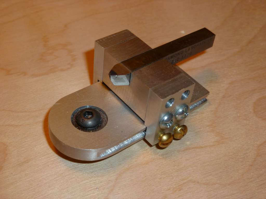
I wanted a ball turning tool for the Sherline lathe, but I didn't really like the design of the Sherline tool. I looked at a few designs for other lathes and based mine on the Taig version. It is similar to the designs I've seen for the 7x lathes, unlike the the "over-the-top" design of the Sherline. The base swings on a bearing which is secured to the cross slide with a screw and T nut. The position of the body is adjustable, as is the position of the tool bit. If the tip of the tool bit is positioned in front of the pivot point of the tool, a concave shape will be created. If the tip of the tool bit is behind the pivot point, a convex, or ball, shape will be created.
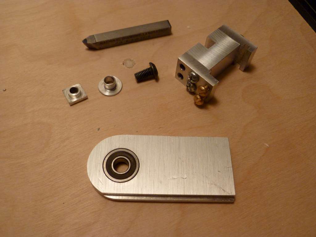
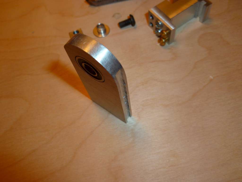
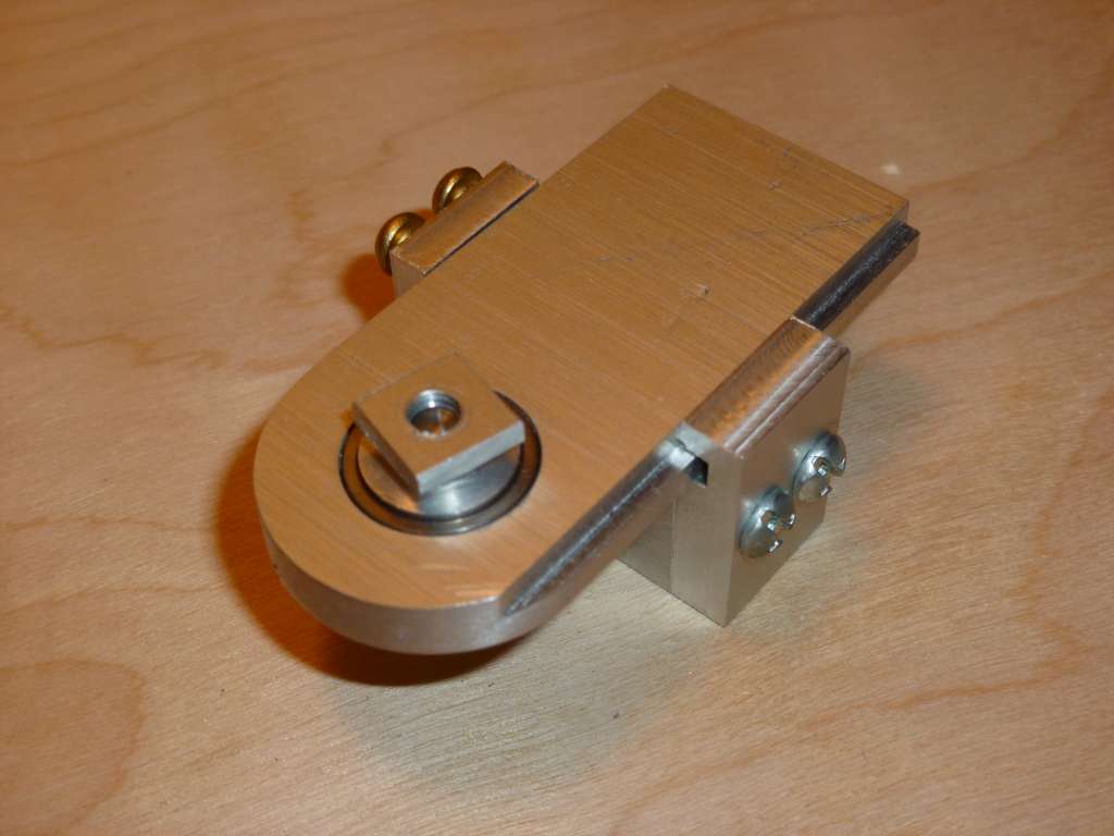
I started by boring a hole, centered across the width of the body, completely through the base to clear the inner bearing race and seal. I bored a concentric hole for the diameter of the bearing. This hole stopped short to leave a rim on the top side for the bearing to rest against and set the proper bearing depth, and was sized for a tight fit. I rounded the end of the base using a rotary table on the mill to allow working closer to the lathe chuck. I milled a rail along the right side of the base and a groove along the left side. The body will ride on the rail and the groove prevents burrs from the adjustment screws from binding. I squared up some stock on the mill for the T nut, then turned the shank, drilled and tapped the hole on the lathe. I turned a bushing with a collar to fit inside the inner bearing race. The bushing fits pretty tight within the bearing and tight to the screw to ensure this tool pivots about the same point every time. The collar keeps the bearing and base from riding on the cross slide and diameter is small enough not to interfere with the outer bearing race.
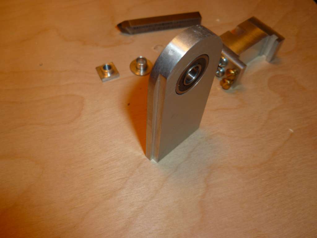
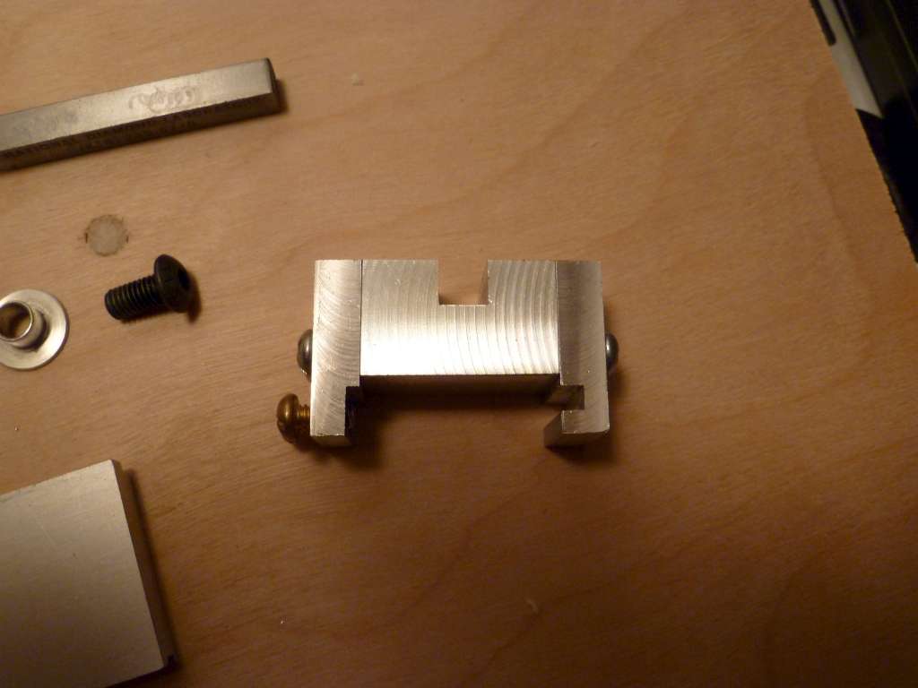
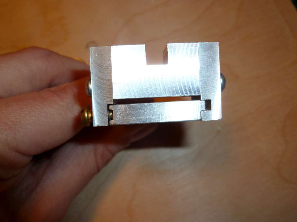
The body would have looked cleaner if it was made from a single piece of aluminum, but I didn't have a piece large enough. The separate side pieces had the advantage of making the groove on the right side easier to mill with the tooling I had on hand. I made measurements so the top of the side pieces, and thus the top of the middle section, would be at the lathe center height. If this was higher, the slot for the tool could be milled deeper, but I think this provided a cleaner look. With the measurements, I milled the groove on the right side and a recess for the left side. One side at a time, I held the middle section aligned with a side piece in a vise and drilled holes for attaching the pieces. I then separated them, enlarged the holes in the side for clearance and tapped the holes in the middle. When I had both sides attached, I drilled and tapped holes for the adjustment screws. With the body attached to the base, I double checked my center height measurements. I milled the slot for the tool bit aligned with the pivot point. If you follow an imaginary line down the center of the tool bit, passing through the tip, it will cross the center of the bearing. I finished up by drilling and tapping 2 holes for set screws to lock the tool bit in place. Click the pictures for larger images.
I started by boring a hole, centered across the width of the body, completely through the base to clear the inner bearing race and seal. I bored a concentric hole for the diameter of the bearing. This hole stopped short to leave a rim on the top side for the bearing to rest against and set the proper bearing depth, and was sized for a tight fit. I rounded the end of the base using a rotary table on the mill to allow working closer to the lathe chuck. I milled a rail along the right side of the base and a groove along the left side. The body will ride on the rail and the groove prevents burrs from the adjustment screws from binding. I squared up some stock on the mill for the T nut, then turned the shank, drilled and tapped the hole on the lathe. I turned a bushing with a collar to fit inside the inner bearing race. The bushing fits pretty tight within the bearing and tight to the screw to ensure this tool pivots about the same point every time. The collar keeps the bearing and base from riding on the cross slide and diameter is small enough not to interfere with the outer bearing race.
The body would have looked cleaner if it was made from a single piece of aluminum, but I didn't have a piece large enough. The separate side pieces had the advantage of making the groove on the right side easier to mill with the tooling I had on hand. I made measurements so the top of the side pieces, and thus the top of the middle section, would be at the lathe center height. If this was higher, the slot for the tool could be milled deeper, but I think this provided a cleaner look. With the measurements, I milled the groove on the right side and a recess for the left side. One side at a time, I held the middle section aligned with a side piece in a vise and drilled holes for attaching the pieces. I then separated them, enlarged the holes in the side for clearance and tapped the holes in the middle. When I had both sides attached, I drilled and tapped holes for the adjustment screws. With the body attached to the base, I double checked my center height measurements. I milled the slot for the tool bit aligned with the pivot point. If you follow an imaginary line down the center of the tool bit, passing through the tip, it will cross the center of the bearing. I finished up by drilling and tapping 2 holes for set screws to lock the tool bit in place. Click the pictures for larger images.